![]() Figure 2 of
Heys, Mol Vis 2004;
10:956-963.
Figure 2 of
Heys, Mol Vis 2004;
10:956-963.
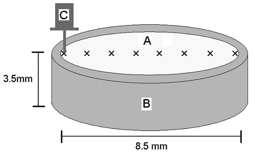
Figure 2. A schematic diagram showing the method used for measurement of lens stiffness
The equatorial section of a lens (A), obtained as illustrated in Figure 1, was held in a metal ring (B) and the lens section was moved across and underneath the DMA probe (C) in 1 mm steps (see Figure 1). At each point a measurement of stiffness was made.
