Figure 3. Two-photon fluorescence (TPF) image processing. A: Raw TPF image. B: Binary mask of noise-filtered and thresholded pixels to isolate TPF-emitting structures. C: Mask from (B) is applied to raw image in (A) to produce the final segmented image for numerical analysis. D–F: Region of interest bounded by white squares is shown at 4× magnification.
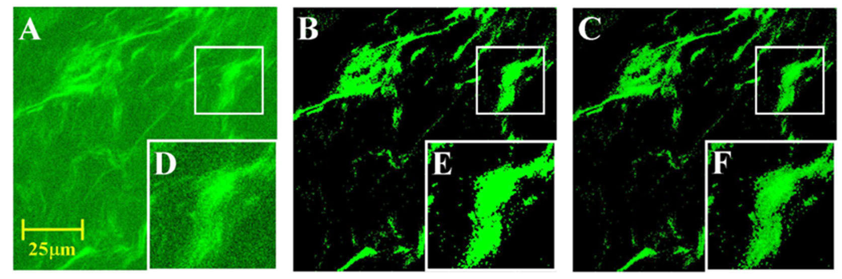
 Figure 3 of
Ma, Mol Vis 2026; 32:169-184.
Figure 3 of
Ma, Mol Vis 2026; 32:169-184.