Figure 7. Zone location by ring and petal. A partially opaque grid used to map the RPE flatmount is overlaid in Adobe Photoshop with
its origin positioned at the center of the optic nerve. The grid consists of concentric circles beginning 400 microns from
the optic nerve. Pairs of double concentric circles, 320 microns apart, create sampling regions. Each subsequent sampling
region begins 20 microns away from the preceding one. This grid along with orientation of the superior petal allows for position
specificity that includes distance from the optic nerve and anatomic orientation. The grid is available for download in Appendix
3.
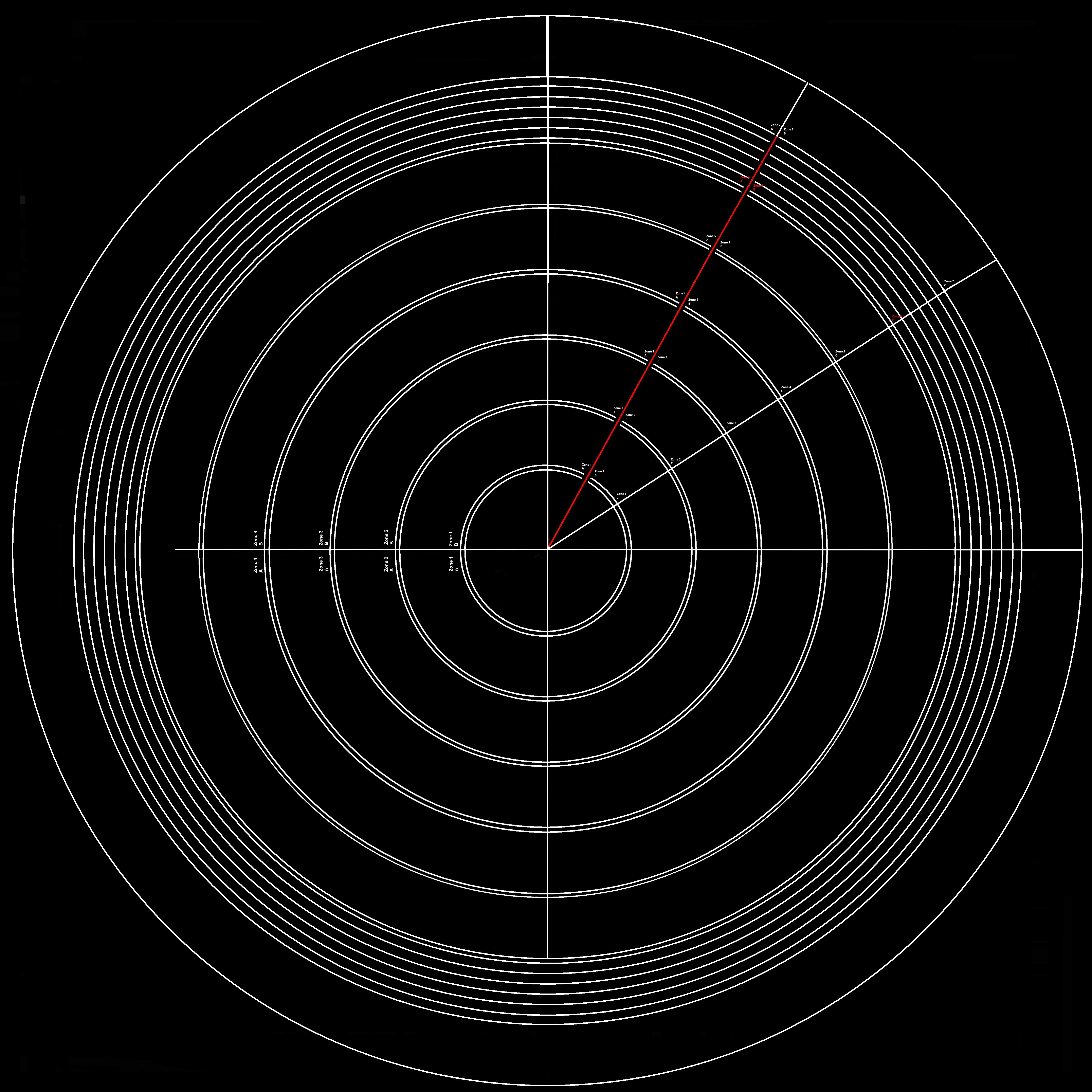
 Figure 7 of
Boatright, Mol Vis 2015; 21:40-60.
Figure 7 of
Boatright, Mol Vis 2015; 21:40-60.