Figure 1. Schematic of sclera
locations. This figure shows the schematic of an inflation
tested left eye, where Rk indicates the labeling of regions. The
positions of points along the scleral edge were calculated for
the initial image (reference configuration) and for the
subsequent images (deformed configurations) in the (e1, e2)
Cartesian coordinate system. The axis of revolution was defined
as the axis passing through the center of the optic nerve head
(ONH) parallel to the axis of the ONH.
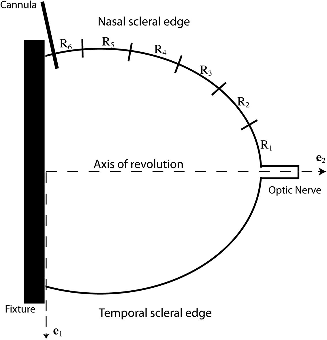
 Figure 1
of Steinhart, Mol Vis 2012; 18:1093-1106.
Figure 1
of Steinhart, Mol Vis 2012; 18:1093-1106.