Figure 2. The subretinal injection
technique. A: Position of the 34 gauge beveled needle is shown
nearly tangential just before lancing the cornea. B: This
schematic illustrates the position of the 35 gauge blunt needle after
puncturing the neural retina and partially inflating the
interphotoreceptor space (the subretinal space) to produce subretinal
blebs. C: Presented is a still image from a video illustrating
penetration of the cornea. D: This panel shows the positioning
of the 35 gauge blunt needle in the center of the anterior chamber. E:
The 35 gauge needle penetrates through the retina into the subretinal
space. F: The 35 gauge needle is removed from the vitreous
after subretinal injection of quantum dots. A small number of quantum
dots are evident in the vitreous that generate a reddish-orange color. G:
Illustrated is a fundus before subretinal injection. The retinal
vessels can be readily detected in the fundus image. A ruddy red
background color can be observed before injection. H: Shown is
the fundus immediately after subretinal injection. The positions of
three blebs surrounding the optic nerve head are located at clock face
positions 4, 8, and 11. Each bleb appears puffy and gray in color with
red vessels between the blebs. The optic nerve head is nearly centered
in the image of the fundus. The imaged mouse eyes are about 3 mm in
diameter.
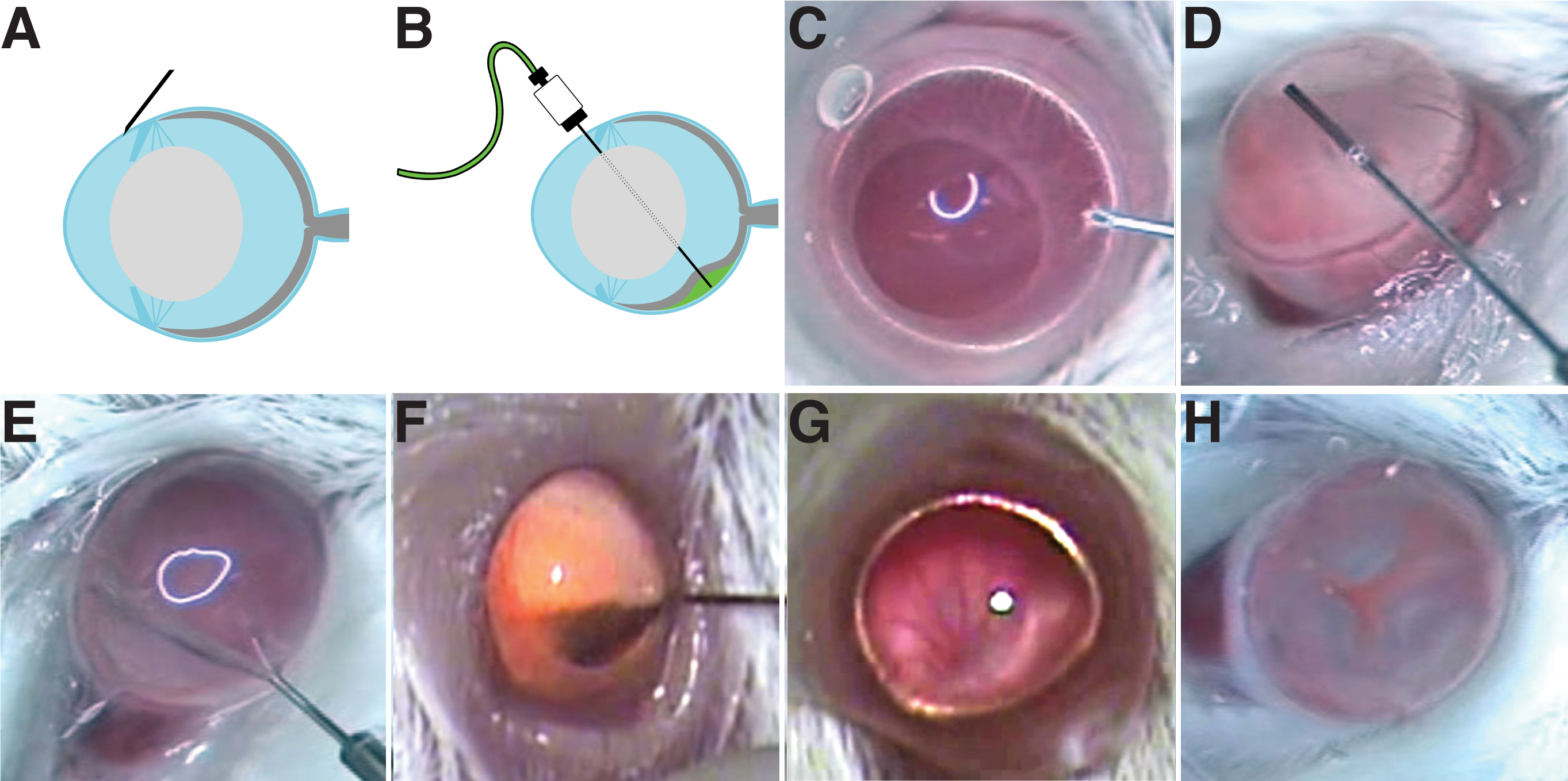
 Figure 2 of Johnson, Mol Vis 2008; 14:2211-2226.