![]() Figure 3 of
Kuszak, Mol Vis 2006;
12:251-270.
Figure 3 of
Kuszak, Mol Vis 2006;
12:251-270.
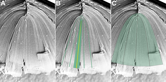
Figure 3. An animated demonstration of scale CADs created from micrographs: Suture patterns
Simplistically described scale CADs of suture patterns are created as follows: Complete and intact suture patterns are examined under a scanning electron microcope (A). The boundaries of straight or planar fibers that define the origin of suture branches are delimited and then filled in yellow from their sutural destinations to the equator. B: Similarly, the boundaries of opposite end curvature fibers that abut and overlap to form suture branches, are delimited and then filled in green from their sutural destinations to the equator. The variable shapes, orientation, length and position of fibers requires that the specimen to be examined at different magnifications. C: The quantitative information on fiber parameters gathered at higher magnification are then combined to create scale CADs consisting of groups of fibers rather than of individual fibers.
Note that the slide bar at the bottom of the quicktime movie can be used to manually control the flow of the movie. If you are unable to view the movie, a representative frame is included below.
| This animation requires Quicktime 6 or later. Quicktime is available as a free download. |